Ensure no weight or load is placed on the truss overhangs, especially in the vicinity of the hip overhang, until all necessary structural members, such as structural fascias, props and roof battens, have been fully installed.
Hip-end connection for low wind area
(wind classification N1, N2, N3 or C1)
Connection of jack, creeper and hip trusses at a hip-end roof for design wind speed N1, N2, N3 or C1 shall be in accordance with the details shown. These details are suitable for a maximum truncated girder station of 3600mm.
The fixing requirements for hip ends in this section are based on the design criteria that are governed by dead loads.
Figure C2-01-01-01
Note 1:
For effective skew nailing, the nail shall be driven into one member not closer than 25mm to no more than 38mm from the area in contact with the adjacent member. The nail shall be driven at an angle between 30° and 45° to the face into which the nail is driven.
Note 2:
Where nails are smaller than the nominated size or other than plain shank nails, or machine driven or both, their performance shall not be inferior to the nail sizes given.
Note 3:
Roof battens or purlins and ceiling battens shall be fixed to trusses in accordance with the approved specification.
Note 4:
Top Chord details of A1 and B1 also apply to GTG (Girder Truncated Girder)
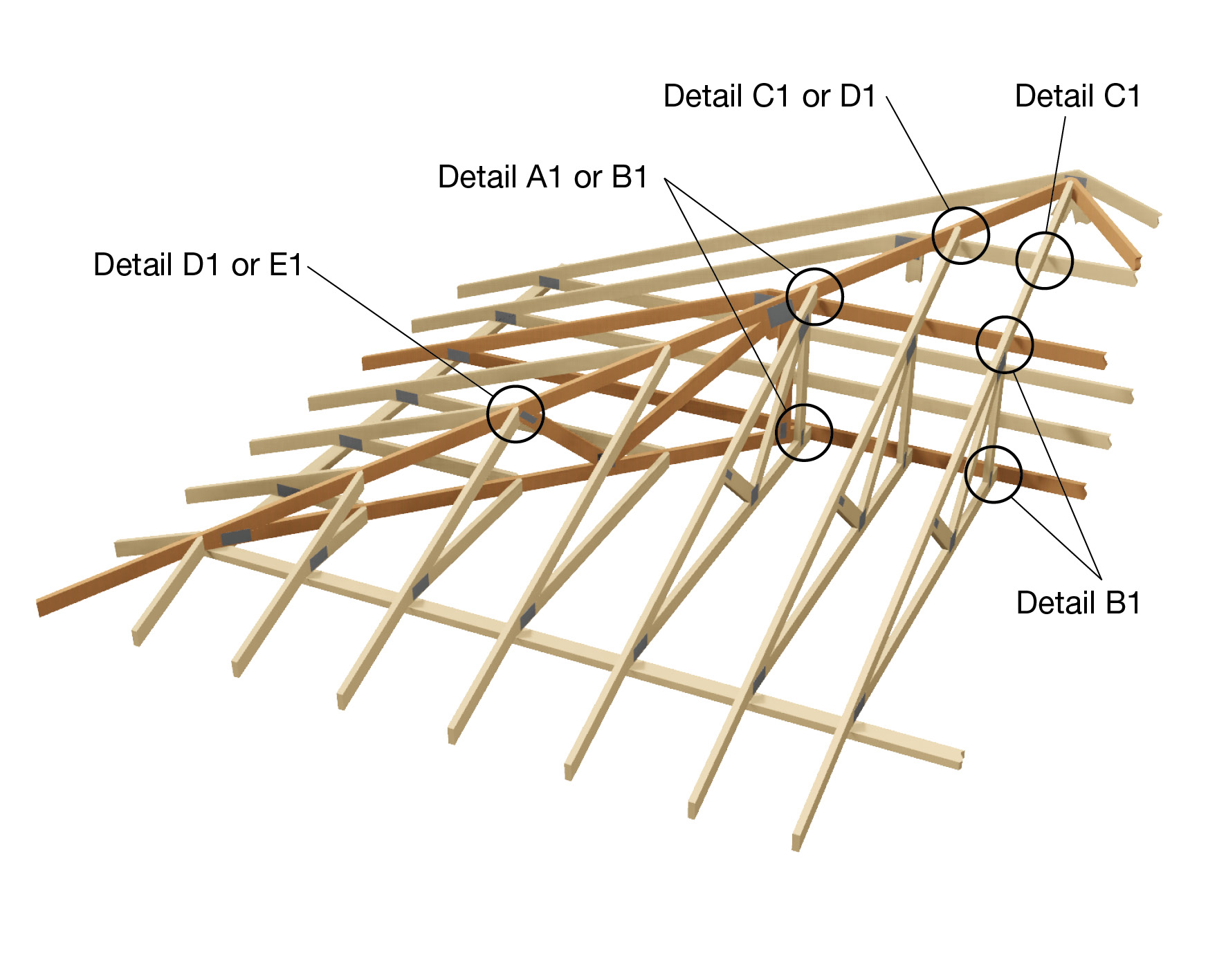
Fully Trussed Hip End Detail Low Wind (N1, N2, N3 or C1)
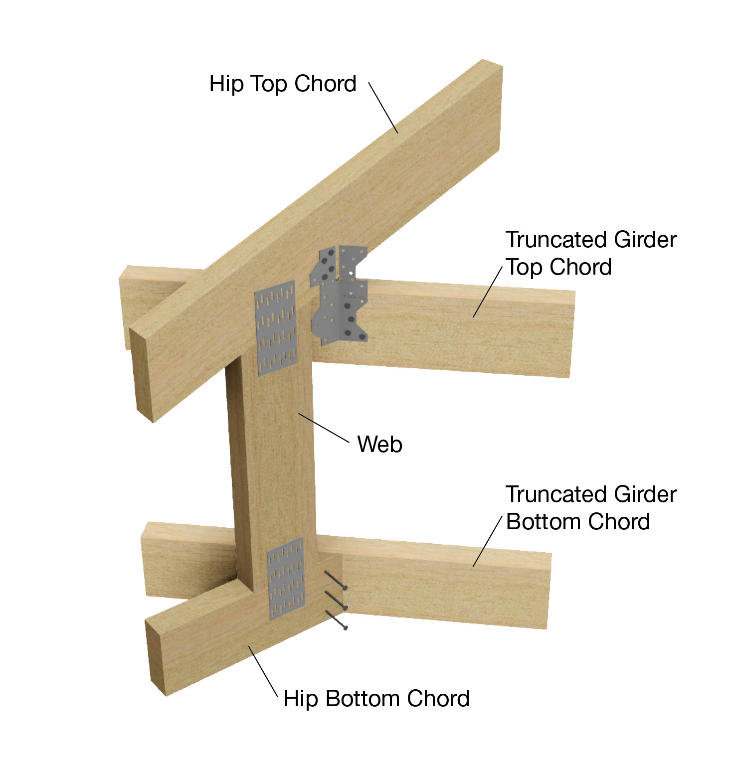
Detail A1
Hip truss to truncated girder truss.
Top Chord - one framing anchor bent to suit, with 4/30mm x 2.8Ø reinforced-head nails into the side of each top chord for truncated girder.
Bottom Chord - 3/75mm x 3.05Ø nails.
Figure C2-01-01-02
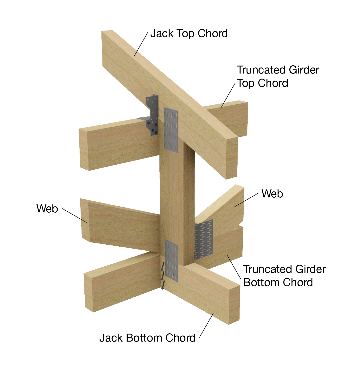
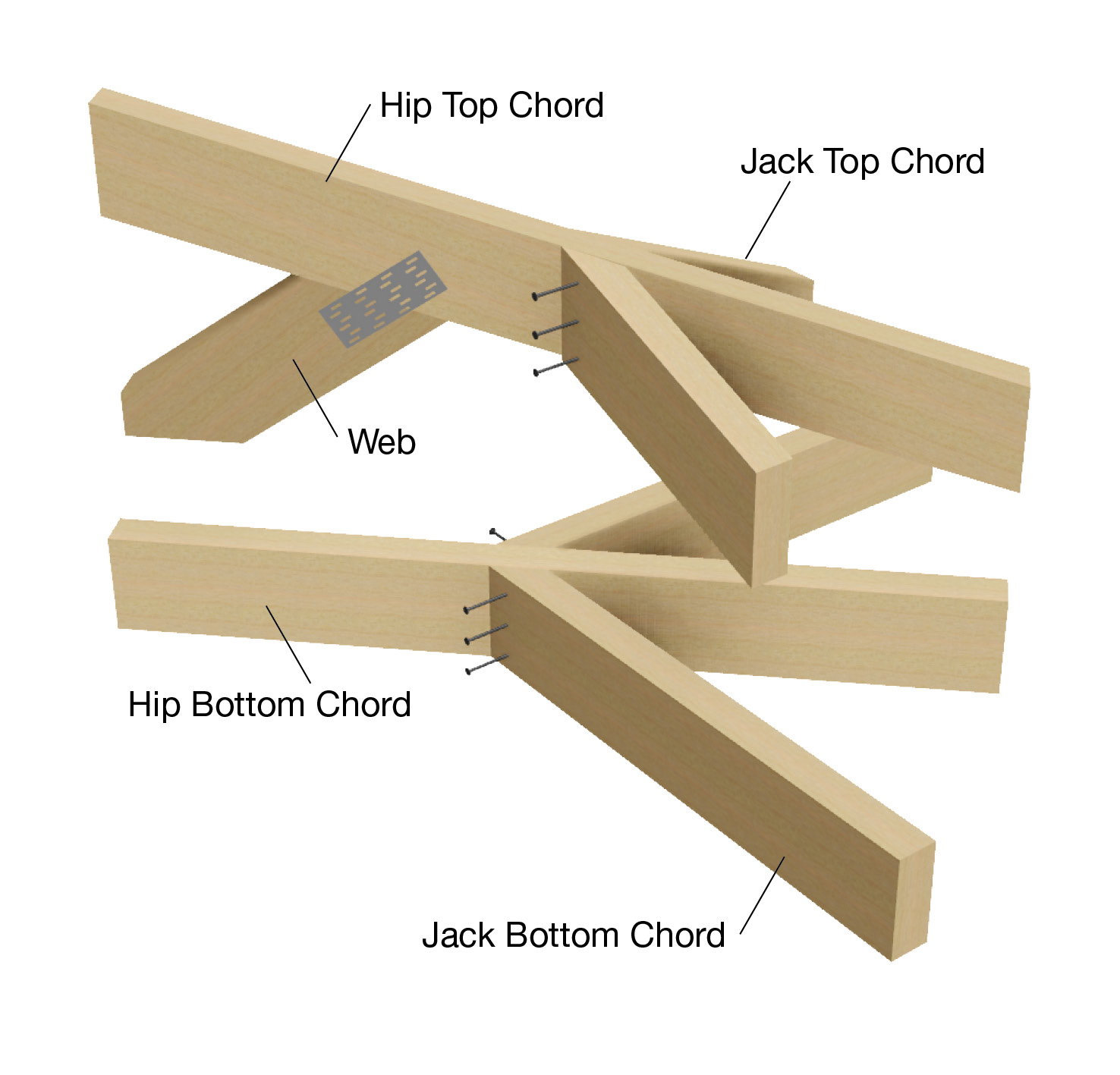
Detail B1
Jack truss to truncated girder truss.
Top Chord - one framing anchor bent to suit, with 4/30mm x 2.8Ø reinforced-head nails into the side of each top chord for truncated girder.
Note: For design wind speed up to N2, tile roofs, truncated girder with spans up to 8000mm and station up to 2400mm, detail C1 may be used.
Bottom Chord - 3/75mm x 3.05Ø in end of jack truss.
Figure C2-01-01-06
Fully Trussed Hip End Detail Low Wind (N1, N2, N3 or C1)
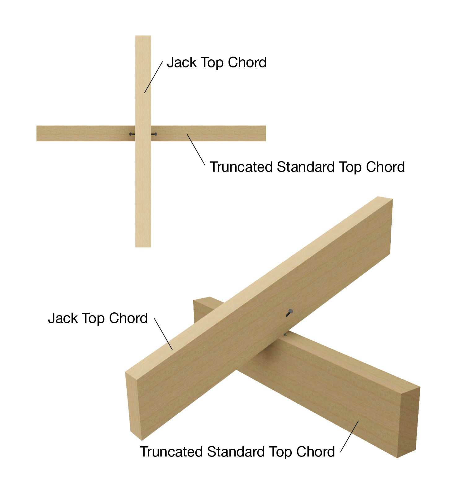
Detail C1
Extended jack truss to top chord of truncated standard trusses.
2/75mm x 3.05Ø skew nails into the side of each top chord.
Note: Follow Detail A1 and B1 when a TS become a GTG (Girder Truncated Girder).
Figure C2-01-01-08
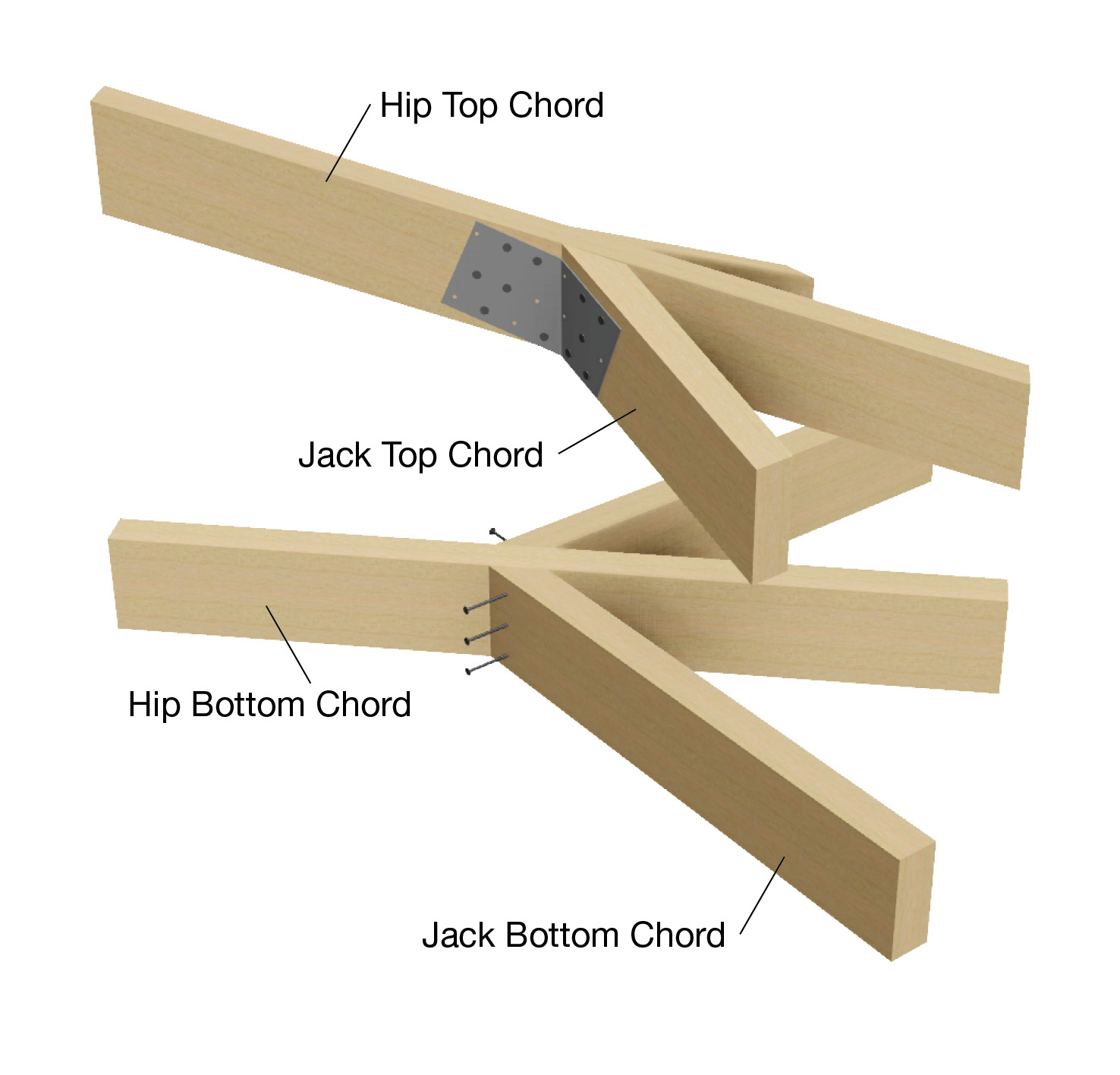
Detail D1
Creeper or jack truss to hip truss (maximum creeper/jack station 1800mm)
Top Chord - 3/75mm x 3.05Ø nails through jack truss top chord into hip truss top chord.
Bottom Chord - 3/75mm x 3.05Ø nails through jack truss bottom chord to hip truss bottom chord.
Figure C2-01-01-09
Fully Trussed Hip End Detail Low Wind (N1, N2, N3 or C1)
Detail E1
Creeper or jack truss to hip truss (maximum creeper/ jack station 3000mm)
Top Chord - fix as detail D1 plus one Mitre plate with 6/30mm x 2.8Ø reinforced-head nails to each top chord.
Bottom Chord - 3/75mm x 3.05Ø nails through jack truss bottom chord to hip truss bottom chord.
Figure C2-01-01-10